Capacitor problems on Bally’s “Hardbody” pinball game
This is my first post talking about pinball, a hobby I picked up when I moved to Seattle. Pinball is a great hobby for an analog electrical engineer like myself for many reasons: first, it’s a great way to meet people (either by challenging other folks to a multiplayer match, or participating in a tournament) and have a fun and cheap night out. Second, the games themselves are completely analog- the player hits a ball around with several flippers and you can even hit or tilt the machine to affect the path of the ball. The analog nature of the game is also evident in the variation that develops between machines of the same game. For example, two tables that start out being exactly the same when they roll off the assembly line will get beat up differently, they’ll break differently, and they’ll get repaired differently. Over time the same game at two different bars will play very differently. An important shot that is easy to make in a certain game at one bar will be very hard at the same game across town, for example. And the best reason the games are so fun is that the full schematics are available online for nearly all games, so if I notice something weird during play I can look up the schematic and try to figure out what may have happened.
I was watching a video about the 1987 pinball game “Hardbody”, a game whose theme is weightlifting and going to the gym and whose design is wonderfully dated to the late 80s. Whether you think that theme is fun or stupid, the game is challenging and has an interesting layout with a large mezzanine level, very fast play, and a very difficult progression of goals. While I was watching Todd Tuckey explain the inside of the game, he mentions that capacitor C30 has to be removed from the sound card otherwise it will cause a nearby chip (the AD7533_DAC) to pop. Looking at the board in the video where that capacitor is located, I thought initially that it was decoupling a thick power trace to ground. I couldn’t imagine why that cap would have to be removed or how it could cause the nearby IC to burn out. So, I looked up the schematic on page 34 of the Bally_1987_Hardbody_Operating_Manual (page 2-8 by the manual’s count) to see what capacitor C30 did. It is a 47mF decoupling capacitor between ground and the OUT1 pin on the AD7533.
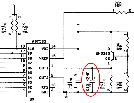
Location of capacitor C30, which as the video mentioned must be removed or it will blow up the sound chip nearby.
Looking at the datasheet for the AD7533, it does not show any recommended configuration in which OUT1 (called I_OUT1 in the datasheet) has a capacitor to ground. The memorandum that was released by Bally to address failure of the AD7533 chip in their machines says that the reason for failure is that during power-down, as the VCC rail falls down to 1.5V and below, the voltage on the capacitor (5V for most games assuming a 5V power supply for the AD7533) is higher than the voltage on the other side of the pin (inside the chip) and apparently the chip was not designed to withstand that. I wonder if a diode should have been used on the output for OUT1 but bipolar operation might preclude this. That is to say, if the output is intended to go above and below 0V then a diode can’t be put in series on the line, at least not inside the IC. But the designer of the board as it is implemented in several games including Hardbody could have include a diode in series with OUT1 to prevent the charged capacitor from leaking back inwards when the game is powered down.
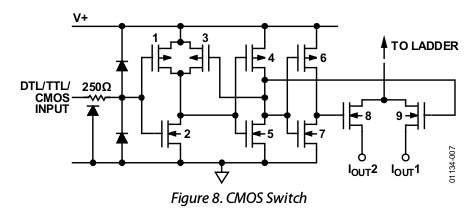
What the inside of the chip looks like behind I_OUT1.
Looking inside the chip to see what might be happening, Figure 8 from the datasheet shown above tells us that I_OUT1 is the source of an N-type MOSFET. The absolute maximum rating for the voltage difference between I_OUT1 and ground is VDD, which would be the 5V power supply. However during shut-down when VDD drops, that 47mF capacitor will have 5V on it and although it will decay through R61 (the 2.7k resistor in parallel with it) it can still push that voltage up through the body diode on MOSFET 9 in Figure 8. The RC time constant from that capacitor-resistor pair is 127s, more than enough time to keep a high voltage and push it up and backwards through I_OUT1 into the R-2R ladder network inside the chip. So when VDD is lowered to zero but the voltage at I_OUT1 remains near 5V, it suddenly violates this absolute maximum rating. It would be interesting to see if this problem still happened if every time the machine was shut down it first output a 0V signal from I_OUT1 to drain the capacitor for a moment. Locking all the bits to “off” would also prevent backflow to V_REF in the ladder network shown below, although the real problem may be impossible to know using only these simplified block diagrams (the real implementation of the circuit probably involves many, many more electronics around each of these MOSFETs for biasing and other reasons).

The R-2R ladder network inside the chip.
This ladder network shown in Figure 7 from the datasheet gives an idea of where that current might backflow into. If the chip is destroyed by having current flow backwards from I_OUT1 toward V_REF, how could this be prevented? Well, obviously removing cap C30 works, but what if there were a larger capacitor between V_REF and ground, or between VDD and ground? The datasheet does not provide a more thorough block diagram of the chip’s internal setup, but perhaps a 47uF or larger capacitor between V_REF and ground would keep V_REF at a higher voltage than I_OUT1 for longer after shutdown, preventing this backflow. That solution was probably not explored by Bally once they discovered that simply removing C30 was all that was needed and could be done without redesigning the board. However if there were a revision of the board then whatever usefulness C30 has could be preserved with this other method.