Circuit Simulations with LTSpice vs. SIMetrix/Simplis
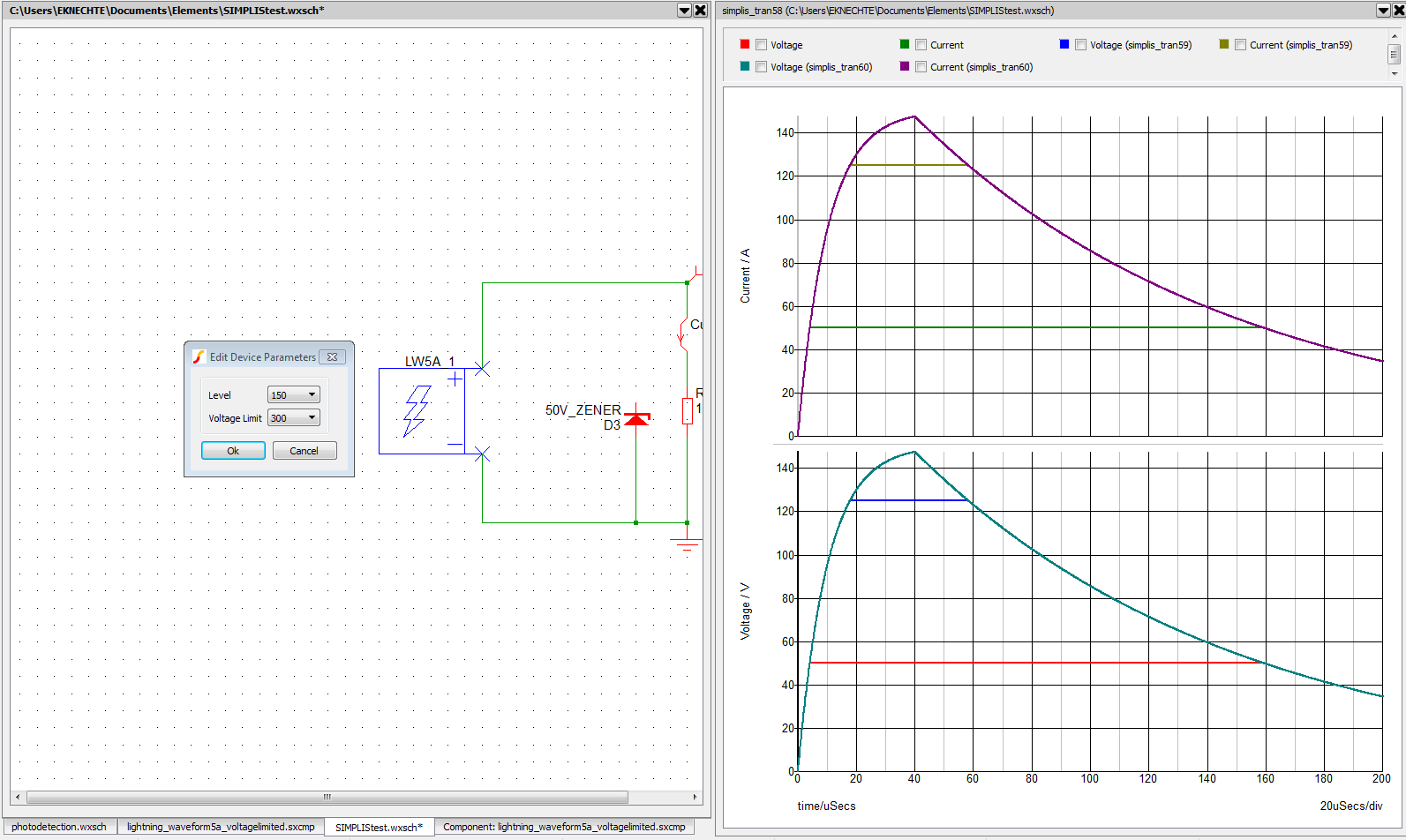
A lightning waveform part, created as a two-terminal device. Waveform 5a has several different current levels with voltage limiting, as shown in the graph on the right.
Building a circuit on a breadboard to test out ideas is really fun, and very useful. But, what if you don’t have a nice oscilloscope at home, or you’re testing out lots of potential circuits with different chips and you don’t want to buy them until you’ve figured out what works? Welcome to the world of simulation. Electronic circuit simulations have been around ever since computers were able to perform rudimentary iterative physics calculations, starting with SPICE, a Simulation Program with Integrated Circuit Emphasis, developed more than 40 years ago.
In school and at my first job I used LTSpice, a variant made by Linear Technologies. I chose it because of the focus on power supply design, something I do for work. Many of my coworkers at my current job use it exclusively because it has such tight integration with LT’s line of ICs for power supply management. I was asked by my manager to try using SIMetrix/Simplis (one program, two names) to create a simulation environment for DO-160 testing. DO-160 is a specification which covers survivability of electronics, specifically for aircraft. The simulations we desired were the lightning tests in which we hit our electronics with five different types of lightning strike to make sure the circuit boards can handle short-duration over-current and over-voltage situations.
SIMetrix/Simplis (why do they have two names? I don’t know, even the website doesn’t clarify the difference or explain why the company doesn’t rationalize it into one program) makes this easy with a part creator, letting me draw a new part, define pins, give it a reference designator template, and attach a simulation model. The simulation models I created by making schematics with current-limited voltage sources and voltage-limited current sources, then enclosing that into a black box model.
I faced a hurdle in getting this to work because the only information available for doing this is a tutorial created by the company that makes the software, but the tutorial is slightly out of date for the current version.
There are of course DRM limitations on the free version of the software. It won’t let the user simulate large circuits, even some of the examples and tutorial circuits, and the software can detect when the user has connected to their PC remotely and it will refuse to start. That’s a problem I discovered when trying to demonstrate my results for my colleagues in a conference room, connecting back to my Windows machine to demonstrate it and it wouldn’t run because it was going over a network! Amazing that Windows lets programs know if there is a remote desktop connection in progress without asking the user, that seems like a security issue.
Overall it’s a very good simulation program and it comes with a very wide library of parts. It can also do Monte-Carlo simulations of circuits to help understand how variance affects performance. For example, if I want to make all my capacitors and resistors 20%-tolerance for cost savings but I’m not sure where I need to spend more money on 10%, 5%, or 1% tolerance parts, the Monte-Carlo simulation can run many times while randomly varying parts within their tolerance ranges and displaying the results. By using this I can figure out where a certain capacitance or resistance is critical, and keep that component at 1% tolerance, while other components may have room for a lot of slop so they can be 20% off nominal.