Radiation controlled Christmas lights
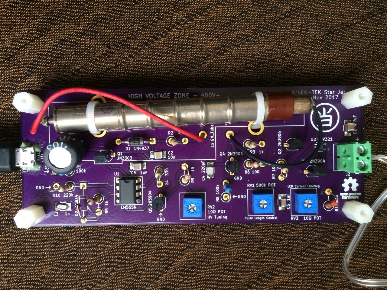
Micro USB connector on the left, Christmas lights attached to the screw terminals on the right. The three poteniometers in blue on the bottom are for adjusting the high voltage boost circuit (not to be used by the end user), pulse duration, and pulse brightness.
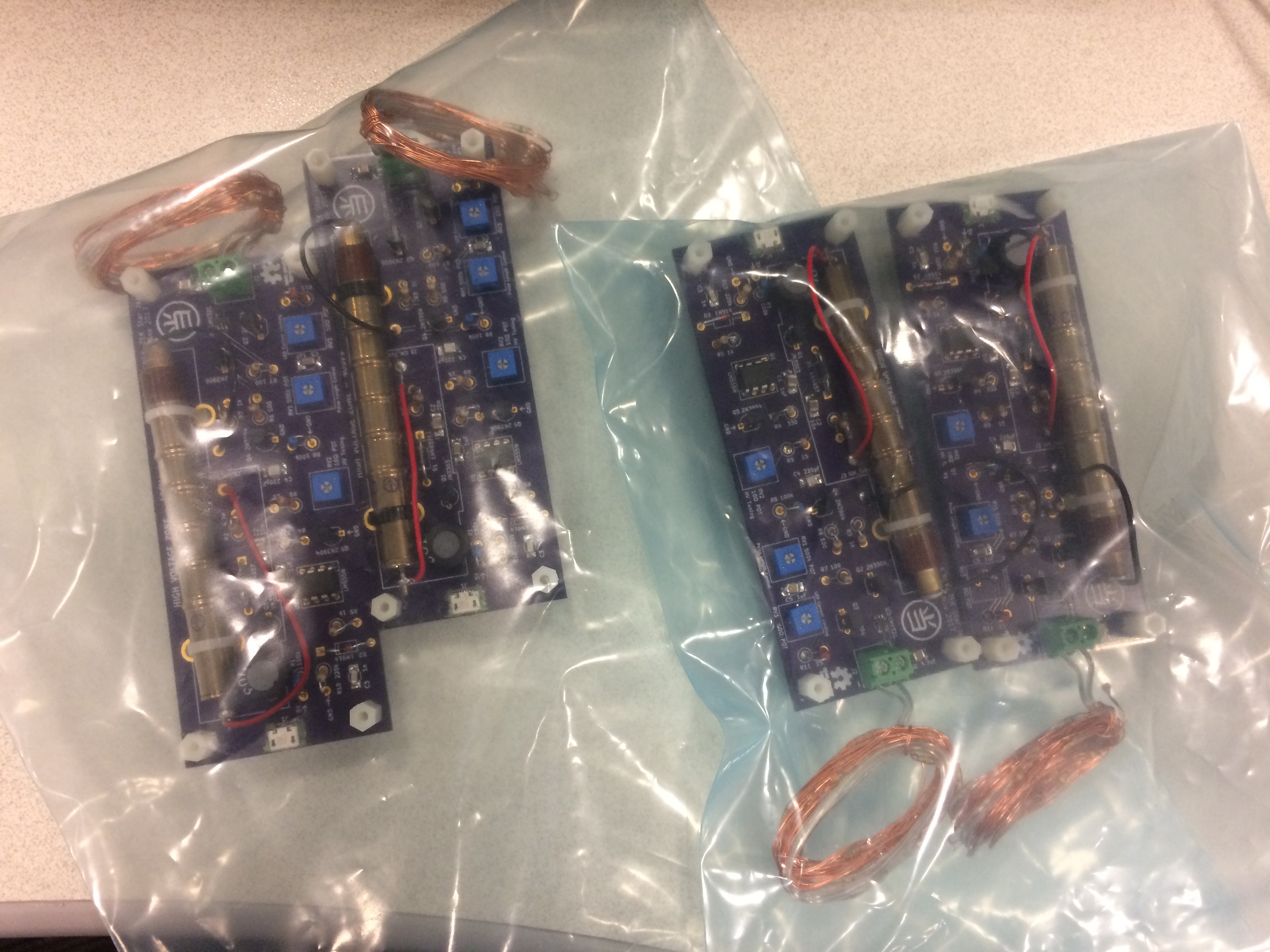
Four identical final boards ready to be boxed up with USB cables and power supplies. And then wrapped and placed under the tree!
From my past posts you can see that I’ve used Geiger-Mueller tubes before to detect ambient radiation. I was inspired to use more of these neat inventions for Christmas gifts for my family- controlling the brightness/dimming of Christmas lights based on frequency of radioactive hits. I made a device that pulses a string of Christmas lights every time a hit is detected, so it looks a bit like a heartbeat. The heartbeat of the cosmos if you will, since many of those high energy ionizing particles come from cosmic rays!
This was an expensive hobby project, around $400 at the end of it. I was helped tremendously by OSH Park since I got some coupons from one of their employees (Thanks Drew!) at the Open Source Hardware Expo in Denver. I made three versions of the PCB to correct small design errors that I discovered and improve the overall visual aesthetics. This project is 100% analog with no software at all. The only two ICs on the board are a 555 timer and an opamp.
Before I even started a layout for a PCB, I had thoroughly simulated and then bread-boarded every aspect of the circuit to verify the design. However I didn’t notice the variability of the GM tubes, since I only tested with one. That one tube gave output pulses of +10V, and so I made an amplifier stage using an NPN BJT that only makes sense if the voltage on the base of the transistor is that high. Once I built the first PCB though I noticed that the lights were only pulsing very dimly, and I was only getting a very weak signal out of the tube of around 1.5V. This was a different GM tube that I had tested with since I had broken the original when I tried to insert it in to fuse holders. That was another design evolution- at first I wanted nice metal fuse holders in which to mount the GM tubes, but those were very cumbersome to solder to the PCB and they were so rigid and strong that inserting the delicate GM tube was hard without denting it. I switched to using zip ties which are cheaper, easier to use, and flexible enough that there’s no risk of breaking another expensive tube.
Anyway after solving those two issues by using zip ties, and adding a better amplifier stage, I got a final design that I liked and I was able to quickly produce 5 of these for my family members. This was my first time producing more than one of something, and forced me to think harder about BOM reduction and cost increases. Going forward, nearly all of my projects will involve production of a PCB to really create a solid, durable item that will last longer than a breadboarded prototype. I was also able to use a state-of-the-art electronics lab that I have access to to perform heavy modifications on my PCB assemblies, including dead-bug mods and frequent use of epoxy. The most modified prototype I kept for myself, to remind me of the design process and it is currently twinkling the Christmas lights in my kitchen.
I wanted to use a nice enclosure to house the boards with a clear top, but those were going to cost me another >$100 for five of them so I just used four nylon standoffs to support the boards on a table. Don’t let a curious pet lick the 400V pin on the Geiger tube or they’ll get a shock equivalent to a strong static electricity jolt!
As always the design files are available on Github.
These gifts are the *best!*. Really enjoying watching the lights flash, and knowing why they do. Waaay cooler than Target!!
Cool! I want to see this in action someday.